Troubleshooting Manual
Warning! According to the law gas boilers fall under ‘controlled service’ appliance, which means that your boiler needs to be installed, commissioned, serviced and repaired by a person having proper qualifications (Gas Safe Registered)
Safety first!
Before starting to work on any Ariston appliance set it into OFF position (move to gauge to off), close valve that supplies fuel and isolate the supply of electricity. Wait till the boiler cools down. Take a note of what fuel is suppose to be used (label on the inside of case side panel). Certain repairs needs to be obtains due to wrong fuel used. You need to pay special attention to:
- check if the information on the reverse of the control panel on your boiler complies with the electric, water and gas mains of your property
- take a note of what gas should be used for your appliance, this information should be provided on the label in the inside of the boiler casing
- this appliance can be installed in a damp environment or close to equipment which spray water or other liquids.
- no objects should be placed on the appliance
- children or inexperienced persons shouldn’t be allowed to use gas boiler
- always have a first-aid treatment near the place you work
- boiler should be immediately switched off you you suspect that it is not working properly
If you smell gas in the room don’t use telephone in the building, turn on the light or any other gas/electrical appliance that may cause any kind of spark. Immediately ventilate the room by opening the doors and windows, close the mains tap and inform your gas supplier by eg. phoning your neighbors phone.
Whenever you are planning to be for an extended time period (from few weeks to few months), you should shut the gas cylinder valve or the mains gas tap. While disconnecting your boiler remember to by unplug it from the mains, alternatively you should turn the mains switch off before carrying out maintenance or cleaning the appliance.
All Ariston boilers models aren’t suitable for external installation. The appliances should be installed on the vertical wall that supports the weight of your appliance (30-60 kg depending on a model). The Ariston boilers can be installed in any room or internal space where IEE Wiring Regulations were followed.
Before installing, exchanging, repairing or upgrading your boiler a competent person should perform all electrical checks in your property. Manufacturer is not liable for damage caused by anomalies in the supply of power or by the failure to earth the appliance. Verify that the residential electrical system is adequate for the maximum power absorbed by the unit, that is indicated on the rating plate. Remember that your appliance operates with alternating current, so connections for the neutral and live wires need to be checked.
Attention! In instances where the power supply cord must be replaced, same type/ specification power cord supply should be provided and applied. Power supply cord must be earthed. Also in instances where the same gas supply is being used by several gas appliances you need to make sure that your gas supply is divided correctly, providing each appliance required gas supply at the same time. Gas pipe going to the boiler need to be in the size specified by manufacturer. Pipes of a smaller size than the boiler inlet connection should not be used.
The Control Panel of your boiler has a 3 digit display. While operating normally the display shows one of three things on the two right hand digits. During Domestic Hot Water status (after opening a tap with hot water) the temperature of the outgoing hot water will appear on display. Temperature will be shown in Celsius. During the summer mode (central heating is permanently off) LED will light. During a demand for Central Heating, the temperature of the central heating flow will appear on display. Temperature will be shown in Celsius. The central heating mode LED lamp will light. During Stand-by (no demand for Central Heating or Domestic Hot Water) simply ‘on’ will appear on display. No LED light will follow. During the flue analysis mode operation ‘sc’ will appear on the display.
Boiler operation
The boiler is capable of operating in two modes: central heating and domestic hot water. Mode is controlled the selector switch on the facia panel. When set to Central Heating mode it will operate in both domestic hot and central heating mode with the domestic hot water mode overtaking central heating mode whenever demand occurs. When set to Domestic Hot Water it will operate only in this mode, central heating won’t be provided.
Central heating mode
Whenever there is a call for heat the pump will automatically start to circulate the water in the central heating system. The air pressure switch will light the burner and fan will start to run at its full speed. The burner is suppose to adjust to provide the system demand. At the moment that demanded temperature is reached, burner will switch off. In instances where there is a need for DHW (domestic hot water) it will override the demand for central heating, but only during the DHW demand. After the hot water tap is closed the boiler will immediately change back to providing CH.
Domestic hot water mode
Whenever a tap with hot water is opened, it is being recognized by the flow switch and at that moment the burner will light and raise the temperature from where it is at the moment of demand to its maximum output. Remember that the burner output is being set by temperature selected by user. When no hot tap water is open, the flow switch and the burner will turn off and the boiler immediately goes back to the central heating mode- if that mode is activated at the moment
Error codes
Whenever your appliance discovers a fault a fault code will be shown on the display. Usually it is a letter and two numers e.g A22 . Each an every time your when fault codes shows a non-volatile (A letter on display) shutdown, you will need to start with resetting the appliance first and continue with assistant of an Ariston Authorised Service Engineer whenever the issue persist or the appliance gets into shutdown mode after reset (re-light try).
Boiler faults starting with letter ‘E’ are not fixable by resetting and therefore your will need to contact the Ariston Authorised Service Engineer straight away giving him the letter and the number of the fault. In an event of a volatile shutdown (E code fault) your appliance will automatically resume operation once the cause was solved, part replaced. In the case of E code faults, you need to switch off the gas at a tap and switch off your boiler until the Ariston Authorised Service Engineer arrives and solves the issue.
Table 1. A list of the fault codes MicroGenus models
| Display | Fault code |
| A01 | No flame after 7 seconds safety time |
| A03 | The heating flow temperature over 103 degrees while operating |
| A91 | The electronic monitoring fault |
| A98 | The electronic monitoring fault |
| A99 | The electronic monitoring fault |
| E02 | Water pressure too low |
| E04 | Domestic hot water temperature probe in open circuit |
| E05 | Domestic hot water temperature probe short circuited |
| E06 | Heating flow temperature probe in open circuit |
| E07 | Heating flow temperature probe short circuited |
| E08 | Heating return temperature probe in open circuit |
| E09 | Heating return temperature probe short circuited |
| E20 | Flame detected with gas valve closed |
| E21 | Error in the electrical connection (live and neutral crossed) |
| E33 | The air pressure switch is closed before the ignition sequence |
| E34 | The air pressure switch does not close when the fan runs |
| E99 | More than 5 RESETS of the boiler in 15 minutes |
Table 2. A list of the fault codes Clas HE R models
| Display | Fault code |
| central heating circuit faults | |
| 1 01 | Overheat |
| 1 03 |
Insufficient circulation
|
| 1 04 | |
| 1 05 | |
| 1 06 | |
| 1 07 | |
| 1 10 | Flow temp. probe circuit open / short circuit |
| 1 12 | Return temp. probe circuit open / short circuit |
| 1 14 | External sensor circuit open / short circuit |
| 1 18 | Heating delivery probe problem |
| 1 P1 |
Insufficient circulation indication
|
| 1 P2 | |
| 1 P3 | |
| internal PCB faults | |
| 3 01 | EEPROM error |
| 3 02 | Comunication error |
| 3 03 | Main P.C.B. error |
| 3 04 | Too many (> 5) resets in 15 minutes |
| 3 05 |
Main P.C.B. error
|
| 3 06 | |
| 3 07 | |
| ignition and detection faults | |
| 5 01 | No flame detected |
| 5 02 | Flame detected with gas valve closed |
| 5 04 | Flame lift |
| 5 P1 | 1st Ignition Failed |
| 5 P2 | 2nd Ignition Failed |
| 5 P3 | Flame cut-off |
Table 3. A list of the fault codes Clas HE System models
| Display | Fault code |
| central heating circuit faults | |
| 1 01 | Overheat |
| 1 02 | Pressure Sens Error |
| 1 03 |
Insufficient circulation
|
| 1 04 | |
| 1 05 | |
| 1 06 | |
| 1 07 | |
| 1 08 | Insufficient water (request filling) |
| 1 10 | Flow temp. probe circuit open / short circuit |
| 1 12 | C.H. Return temp. probe circuit open / short circuit |
| 1 14 | External sensor circuit open / short circuit |
| 1 16 | Floor Thermostat contact open |
| 1 18 | Heating delivery probe problem |
| 1 P1 |
Insufficient circulation indication
|
| 1 P2 | |
| 1 P3 | |
| dometsic hot water circuit faults | |
| 2 02 | Bottom storage temperature probe open / short circuit |
| 2 04 | Solar collector temperature probe open / short circuit |
| 2 07 | Solar collector overheating |
| 2 08 | Collector frost protection temperature |
| internal PCB faults | |
| 3 01 | EEPROM error |
| 3 02 | Comunication error |
| 3 03 | Main P.C.B. error |
| 3 04 | Too many (> 5) resets in 15 minutes |
| 3 05 |
Main P.C.B. error
|
| 3 06 | |
| 3 07 | |
| extrnal PCB faults | |
| 4 07 | Room sensor circuit open 7 short circuit |
| ignition and detection faults | |
| 5 01 | No flame detected |
| 5 02 | Flame detected with gas valve closed |
| 5 04 | Flame lift |
| 5 P1 | 1st Ignition Failed |
| 5 P2 | 2nd Ignition Failed |
| 5 P3 | Flame cut-off |
| air inlet/ flue gas outlet faults | |
| 6 04 | Insufficient fan speed |
| 6 10 | Thermofuse open |
| multi-zone heating faults | |
| 7 01 | Zone 2 outgoing sensor defective |
| 7 02 | Zone 2 return sensor defective |
| 7 03 | Zone 3 outgoing sensor defective |
| 7 04 | Zone 3 return sensor defective |
| 7 05 | Hydraulic separation sensor defective |
| 7 06 | Zone 2 overheating |
| 7 07 | Zone 3 overheating |
Table 4. A list of the fault codes Ariston Combi models
| Display | Fault code |
| A01 | Overheating lock out / Heat exchanger thermo fuse |
| A03 | No flame after safety timer |
| A18 | 3 “flames in progress” disappearances in 1 operating cycle |
| A37 | CPU fault |
| A39 | MCU fault 1 |
| A40 | MCU fault 2 |
| A41 | Fan error |
| E02 | Pump protect (display after 40s.) |
| E04 | No flame detection |
| E05 | Anti freezing system, pump on |
| E06 | Anti freezing system, pump and burner on |
| E07 | No water circulation in primary circuit |
| E08 | No water in the primary circuit |
| E09 | DHW sensor open circuit |
| E10 | DHW sensor short circuit |
| E11 | Flow sensor open circuit |
| E12 | Flow sensor short circuit |
| E13 | Return sensor open circuit |
| E14 | Return sensor short circuit |
| E15 | Outdoor sensor open circuit (if fitted) |
| E16 | Outdoor sensor short circuit (if fitted) |
| E18 | Flame lift |
| E20 | Flame detect with gas valve off |
| E29 | Communication problem with offset unit |
| E30 | Communication problem with offset unit |
| E33 | Floor heating thermostat open circuit (if fitted) |
| E37 | Communication problem with the main PCB |
| E38 | Reset button pressed 5 times in 15 minutes |
After repair of each fault starting with E or after parts replacement and annual service following checks should be run before the initial startup:
– when the system is full the screw present on the automatic air valve was loosened
– all electrical connections were properly fixed and earth wire is in place, connected to earthing system
– the water pressure in the system is up to the appropriate level – so it is above 1.5 bar
– the gas cock is closed
– supply power to the appliance is switched on- knob is in the ON position
After switching ON the appliance, display will react by showing ON. Turn the C knob to maximum and switch the time clock to constant and turn up the room stat where fitted. After about 7-10 seconds, the boiler will signal a shutdown due to ignition failure. Leave the boiler as it is until all of the air has been bled from the system.
– loosen the cap on the head of the pump to eliminate any air pockets, repeat this procedure in order to beed the air extend from the radiators
– open the hot water taps for a a period of couple of minutes, check if water is hot and that the system pressure hasn’t dropped. If dropped open the filling loop again to bring the pressure back up to minimum 1.5 bar
– open all radiator valves
– turn on the gas cock and check the seals on the connections with an approved soap solution and eliminate any leaks
– reset the appliance by pressing the reset button and your boiler will re-attempt ignition. If the burner does not light the first time, wait 1 minute and repeat the procedure
– check the minimum and maximum burner pressure values. Adjust if necessary
Anti-frost device
All Ariston boilers are fitted with anti frost device. This device gets activated when the water temperature falls under 3 ̊C. In those instances the burner ignites at the minimum power till a temperature of approximately 33 ̊C is reached in the in the heating circuit of your boiler. Take a note that anti frost device will work only when following criteria are met: boiler is powered up, gas is turned on and there is enough pressure in the system.
Diverter valve and pump protection
Diverter valve and pump seizing is prevented by activating appliance’s pump for about 25 seconds every 20-21 hours after it’s last operation. After pump activation diverter valve is being activated following the same logic.
Heating system draining
Some of the maintenance works will require your system to be drained. It can be achieved by following the steps below:
- Turn off the boiler
- Attach a hose pipe and open the drain valve
- Drain the system where the lowest points are present
In instances when your heating system won’t be used for extended period of time, espcially during the heating season it is advised to add some antifreeze substance containing an ethylene glycol base to the water in the heating pipe work and radiators. It is particularly important when the the ambient temperature drops below 0°C. Using an ethylene glycol base makes the draining of the entire system unnecessary.
Domestic hot water system draining
Some of the maintenance works will require your system to be drained. Also your system should be drained whenever the temperature drops down below the freezing point. It can be achieved by following the steps below:
- Turn off the general water valve for the household plumbing system
- Turn on all the hot water taps
- Empty the remaining water from the present lowest points in the system
The condensate trap cleaning
The trap is accessed by emptying the condensate bowl located in the bottom section. It should be washed with water and detergent. Remember to replace the condensate collection bowl in its housing. Whenever you don’t use your appliance for longer period of time pay attention that the trap must be filled before being used again. A lack of water in the siphon is dangerous and may cause exhaust gases to be released into the atmosphere.
Appliance annual service
For safety and economy reasons your appliance should be serviced once every year. The Ariston Authorised Service Engineer will inspect and clean or/and replace all needed parts. Annual service usually takes up to 3 hours and can easily be performed during the non heating period.
Parts replacement
Warning! Before start to work on any Ariston boiler first set the boiler into OFF position, close the valve supplying gas and isolate electrical supply Remember that any service and maintenance work (under or over guarantee) must be carried out only by an authorized boiler technician (GasSafe Registered), ideally an Ariston Authorised Service Engineer. Boiler individual parts were designed to work smoothly for years, however parts should be replaced when faults develop, always by using Ariston original spare parts The error code section above will help you to locate which component is the cause of any malfunction, and instructions below will help you to remove, inspect and replace where necessary.
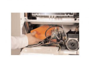
Gaining general access- removing the front panel
In order to perform any inspection, part replacement you first need to gain a general access the inside of the boiler. In order to do it you need to follow the steps below:
1. Unscrew the fastening screws “A” of the control panel located on the lower part of the panel itself as shown on the picture below
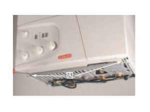
2. Move the control panel downward and when pull it forward.
3. Rotate on two lateral hinges
4. Put the panels aside in a horizontal position,
5. You now have an access to the inner parts of the boiler.
The combustion cover replacement
1. Isolate the appliance and gain general access by removing the front panel
2. Remove the E screws as shown on the picture
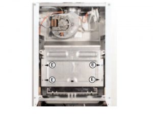
3. Lift off the combustion cover
4. Replace the combustion cover with the new one
5. Re-assemble in reverse order
The burner and jets replacement
1. Isolate the appliance and gain general access by removing the front panel
2. Remove the F screws from the burner as shown on the picture
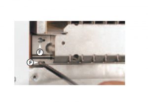
3. Remove the burner
4. Disconnect the electrodes
5. Remove the jets. You should use socket spanner number 7
6. Replace each or all in reverse order
7. Re-assemble in reverse order
The electrodes replacement
1. Isolate the appliance and gain general access by removing the front panel
2. You need to unscrew and slide the burner as described in the section above
3. Remove rubber gasket as shown on the picture
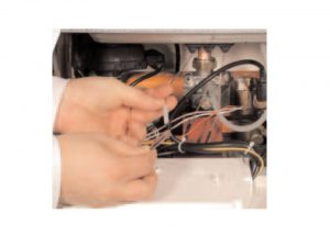
4. Disconnect the cable at its connection point close to the PCB in order to remove the detection electrode
5. Remove all necessary screws
6. Gently slide the electrode downward
7. Replace each or all in reverse order
5. Re-assemble in reverse order
The main heat exchanger replacement
1. Drain the boiler
2. Isolate the appliance and gain general access by removing the front panel
3. Remove the side panels
4. Remove the overheat I thermostat sensor as shown on the picture below
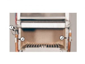
5. Remove the J clips
6. Release the connection nut
7. Pull down the pipe
8. Pull the exchanger out
9. Replace by repeating above steps in reverse order. Pay extra attention to the listed below
– centre the electrode is easily breakable part to position it in hole carefully
-make sure right hand electrodes and left hand electrodes are facing each other, otherwise they won’t give the spark
– electrode connennection points it completely/ rubber gasket seals the clable
– cables are correctly connected
10. Re-assemble in reverse order
The air pressure switch replacement
1. Drain the boiler
2. Isolate the appliance and gain general access by removing the front panel
3. Disconnect the all electrical connections and silicone pipes from their connection points as shown on the picture below
4. Remove screws on the top of the sealed chamber
5. Lift out the air pressure switch
6.Unscrew to remove the switch from the plate
7. Replace air switch pressure
8. Re-assemble in reverse order
The fan replacement
1. Isolate the appliance and gain general access by removing the front panel
2. Disconnect electrical connections and silicone pipe as shown on the picture below
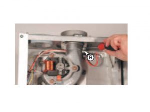
3. Remove R screw and remove the fan collar clamp
4. Remove the screws
5. Remove fan and mounting plate
6. Replace and re-assemble in reverse order
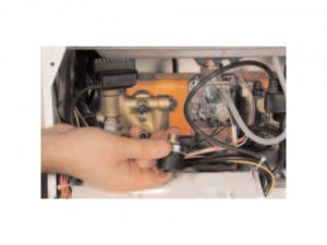
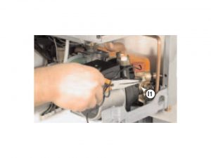
The gas valve replacement
1. Isolate the appliance and gain general access by removing the front panel
2. Remove the spark generator in appliances with Honeywell Gas Appliance
3. Ignition leads should be disconnected by pulling those upward as shown on the picture below
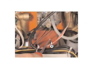
4. Remove the U screw as shown on the picture above
5. Remove the spark generator by pulling forward from the gas valve
6. Replace and re-assemble in reverse order
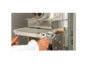
The D.H.W. (secondary) exchanger replacement
1. Isolate the appliance and gain general access by removing the front panel
2. Remove the screws
3. Disconnect the cable
4. Push the insulation of the exchanger towards the rear of the boiler, and lift upwards and remove from the front of the boiler
5. Push the exchanger towards the rear of the boiler, and lift up. Remove it away from the boiler’s front side
6. Before replacing the exchanger you need to make sure that O rings are in the right condition. If that is not the case replace it
7. Replace and re-assemble in reverse order
The pump pressure switch replacement
1. Isolate the appliance and gain general access by removing the front panel
2. Remove the pump pressure switch electrical connections
3. Unscrew the pump pressure switch by using a spanner on the nut
4. Remove the pump pressure switch
5. Replace and re-assemble in reverse order
The safety valve replacement
1. Isolate the appliance and gain general access by removing the front panel
2. Disconnect the discharge pipe work from below the boiler
3. Unscrew the A1 fixing screw as shown on the picture below
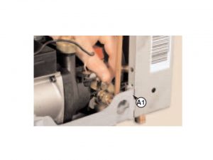
4. Pull the valve upwards for removal
5. Replace and re-assemble in reverse order
The automatic air vent replacement
1. Isolate the appliance and gain general access by removing the front panel
2. Remove the U-clip as shown on the picture below
3. Remove valve complete with float using a screwdriver
4. Replace and re-assemble in reverse order
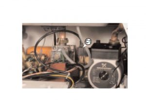
The pump replacement
1. Isolate the appliance and gain general access by removing the front panel
2. Remove the C1 electrical connection as shown on the picture below
3. Release the nut
4. Remove the retaining clip from the bottom of the boiler
5. Remove the screw
6. Remove the U-clip and the pressure gauge connection
7. Remove the automatic air vent
8. Remove the pump.
9. Replace and re-assemble in reverse order
The pressure gauge replacement
1. Isolate the appliance and gain general access by removing the front panel
2. Remove the I1 U-clip as shown on the picture below
3. Lift the pressure gauge from the rear of the control panel using a screwdriver
4. Replace and re-assemble in reverse order
The expansion vessel replacement
1. Isolate the appliance and gain general access by removing the front panel
2. Release nut
3. Remove back-nut
4. Remove the expansion vessel
5. Disconnect the overheat thermostat electrical connections
6. Remove the thermostat from its mounting by releasing the securing clip
7. Replace and re-assemble in reverse order
The P.C.B. replacement
1.Isolate the appliance and gain general access by removing the front panel
2. Remove the inspection cover from the reverse of the control panel, unscrew all necessary screws
3. Unplug all electrical connections from the P.C.B
4. Carefully unplug the EEPROM key
5. Remove the screws as shown on the picture below
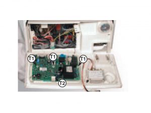
6. Separate the facia panel from the rear of the control panel
7. Remove the main P.C.B., unscrew the T1 screws
8. Unscew the display P.C.B. T2 mounting screws and disconnect the P.C.B. connection cable
9. Remove the display P.C.B.
10.Replace P.C.B.
11.Refit the EEPROM key “R1”
12. Re-assemble in reverse order
Removing the time clock
1. Isolate the appliance and gain general access by removing the front panel
2. Disconnect the electrical connections from the clock as shown on the picture below
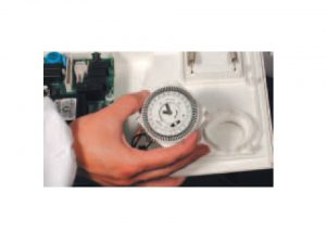
3. Remove screws
4. Lift the time clock out from the control panel
5. Replace and re-assemble in reverse order
Safety first! Following operational checks should be held after each part replacement attempt
1. The complete flue system should be visibly checked for soundness. What’s more we recommend to check the entire gas installation, that includes purge test, test for soundness and the gas meter inspection. Gas cock that was provided with the connection kit should be opened to the appliance and check the gas connector on the appliance for leaks. When the installation and filling are completed turn on the central heating system and run it until the temperature has reached the boiler operating temperature. The system must then be immediately flushed through, standard flushing procedure should be obtained. During this operation, it is recommended to use a central heating flushing detergent, for example Fernox Mb1. Fernox’s function is to dissolve any foreign matters that may be inside of the system. Other detergents can create serious issues to many components and to the pump itself. We also recommends inhibitors usage to prevent corrosion. Corrosion can highly damage not only boiler, but the whole system. Not using proper detergents or inhibitors may cause boiler’s warranty invalidation.
2. On Central Heating circuit allow the system to warm up and adjust the Central Heating temperature control knob, you need to verify ifthe burner modulates down and up between the low and high settings
3. Very if correct range rate is set for the central heating thermal power
4. Run the Domestic Hot Water and adjust to the correct water flow rate, adjust the knob of the Domestic Hot Water temperature control to verify if the burner modulates down and up between the low and high settings
5. Balance the Central Heating system until all return temperatures are correct and equal
6. Turn the OFF/ON button to the OFF position, now the pressure gauge should be disconnected, screw should be re-tighten screw and boiler relighted
7. Perform sound check once more for domestic hot water and central heating
8. Verify air supply in presence in the combustion and presence of the gas flame. In instances where external controls have been disconnected, re-connect those and test
9. Refit boiler casing. Restart the boiler